Variable Dc-Dc Transformers and
Their Use as Modulators
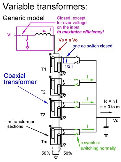
The variable dc-dc
transformer has boost modulator characteristics. It is the
preferred
output modulator for power converters requiring isolation and having a
large step-down voltage ratio.
The primary excitation operates at 100 % duty-cycle, for maximum
efficiency. The effective turns ratio is controlled on the
secondary
side, so no feed-back signals need to cross the isolation barrier.
The efficiency of the variable dc-dc transformer is highest when its
effective turns ratio is maximum, just as in a boost converter
operating at nearly 0 % duty-cycle. If the input voltage droops,
the
effective turns ratio is reduced to maintain the output voltage
regulation. Because the effective turns ratio is lower, the input
current increases and efficiency is reduced.
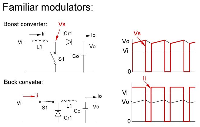
In the familiar boost and buck converters, the duty-cycle of the switch
S1 is pulse width modulated
to regulate the output voltage Vo. The entire current and voltage
is switched on and off during each switch cycle. At high
duty-cycles in the boost converter and low duty-cycles in the buck
converter, the rms current and voltage are high and efficiency is poor.
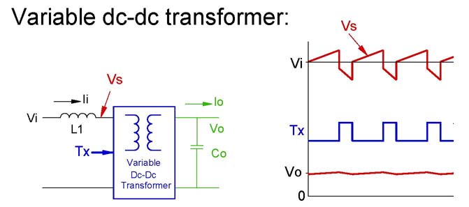
In the variable dc-dc transformer, the effective turns
ratio is modulated between two discrete steps of many to
regulate the
output voltage. Because the effective turns ratio varies by a
small step, the voltage and current do not change nearly as much and
the rms current and voltage are close to their dc values. At low
effective turns ratios, the input current increases and the efficiency
is reduced.
SPICE simulations:
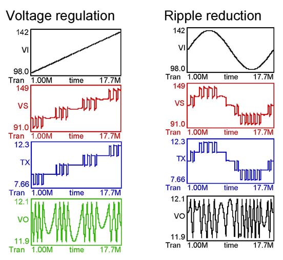
The graphs above are copied and pasted form SPICE simulations using the
probe function.
In the graphs on the left, the input voltage Vi is varied from 100 to
140 volts. The effective turns ratio Tx is modulated between 8 : 1 and
9 : 1, then between 10 : 1 and 9 : 1 and so forth. The primary
voltage is Vs and the output voltage is regulated at 12 V dc.
In the graph on the right, the input voltage has an extreme ac ripple,
100 to 140 volts. The effective turns ratio modulates in steps to
regulate the output voltage to 12 V dc.
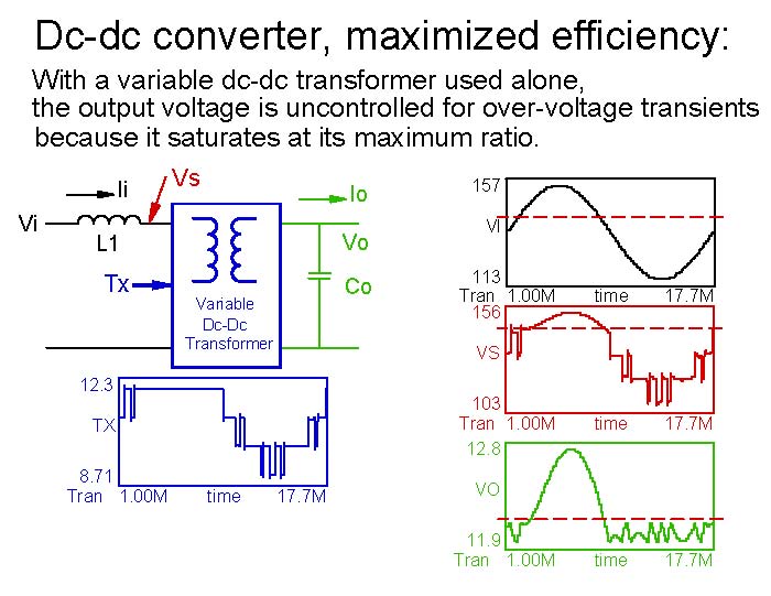
The variable dc-dc transformer is most efficient at its maximum
effective turns ratio, but just as with a boost converter operating
near 0 % duty-cycle, it saturates with over-voltage transients and no
longer regulates. The output is determined, and follows the input
voltage like a fixed ratio dc-dc transformer. The graphs above
show the result.
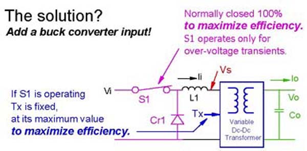
The solution is to put a buck converter as an input stage, and have it
operate at 100 % duty-cycle except when there is an over-voltage
transient condition.
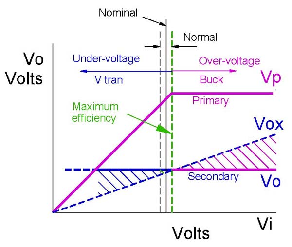
Vox is the curve that the output voltage Vo would follow with a fixed
ratio dc-dc transformer alone. To the left of the vertical green
line, the variable dc-dc transformer regulates the output voltage
Vo. To the right, the buck regulator operates. Efficiency
is maximized at the green line, and is very good over the normal
operating range.
Design examples:
The "generic" variable dc-dc transformer can vary its effective turns
ration over the full range, but the input currents get very large at
low input voltages, unless there is load shedding, so its use at very
low effective turns ratios should be restricted to transient conditions
or "hold-up" time.
Coaxial Transformer
construction:
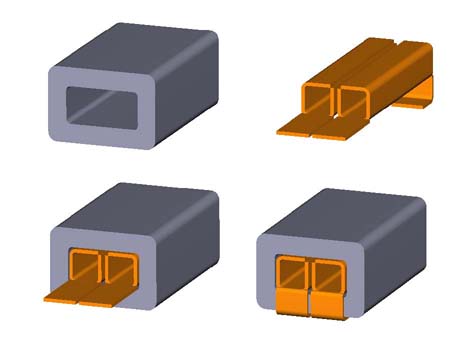
The coaxial transformer is very simple. The secondary windings
are formed stampings inserted into a simple ferrite core.
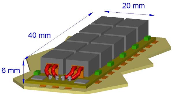
The cores may be mounted on a printed circuit board. The
transformer shown is for a 1 V dc output at 150 A dc.
More design examples:
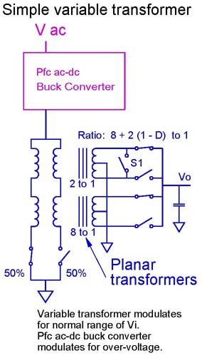
If the input voltage is fairly precise (+/- 10 %), a simple two part
variable dc-dc transformer can provide a precise regulated output
voltage Vo.
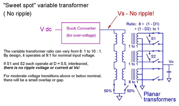
A variant of the simple variable dc-dc transformer has three
transformer elements. When operated at nominal input voltage,
there is no ripple and the variable dc-dc transformer regulates for +/-
10 % variations in the input voltage. A buck converter input
stage can be used for over-voltage transient protection.
